
Forms of Corrosion
The forms of corrosion described here use the terminology in use at NASA-KSC. There are other equally valid methods of classifying corrosion, and no universally-accepted terminology is in use. Keep in mind that a given situation may lead to several forms of corrosion on the same piece of material.
Uniform Corrosion
This is also called general corrosion. The surface effect produced by most direct chemical attacks (e.g., as by an acid) is a uniform etching of the metal. On a polished surface, this type of corrosion is first seen as a general dulling of the surface and, if allowed to continue, the surface becomes rough and possibly frosted in appearance. The discoloration or general dulling of metal created by its exposure to elevated temperatures is not to be considered as uniform etch corrosion. The use of chemical-resistant protective coatings or more resistant materials will control these problems.
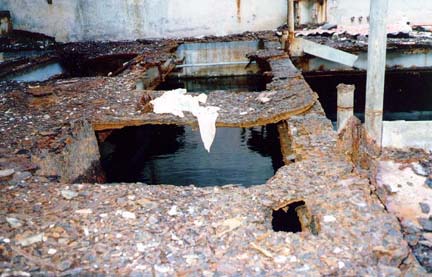
While this is the most common form of corrosion, it is generally of little engineering significance, because structures will normally become unsightly and attract maintenance long before they become structurally affected. The facilities shown in the picture below show how this corrosion can progress if control measures are not taken.
Galvanic Corrosion
Galvanic corrosion is an electrochemical action of two dissimilar metals in the presence of an electrolyte and an electron conductive path. It occurs when dissimilar metals are in contact.
It is recognizable by the presence of a buildup of corrosion at the joint between the dissimilar metals. For example, when aluminum alloys or magnesium alloys are in contact with steel (carbon steel or stainless steel), galvanic corrosion can occur and accelerate the corrosion of the aluminum or magnesium. This can be seen on the photo above where the aluminum helicopter blade has corroded near where it was in contact with a steel counterbalance.
Galvanic Series In Sea Water
Noble
(least active)
Platinum
Gold
Graphite
Silver
18-8-3 Stainless steel, type 316 (passive)
18-8 Stainless steel, type 304 (passive)
Titanium
13 percent chromium stainless steel, type 410 (passive)
7NI-33Cu alloy
75NI-16Cr-7Fe alloy (passive)
Nickel (passive)
Silver solder
M-Bronze
G-Bronze
70-30 cupro-nickel
Silicon bronze
Copper
Red brass
Aluminum bronze
Admiralty brass
Yellow brass
76NI-16Cr-7Fe alloy (active)
Nickel (active)
Naval brass
Manganese bronze
Muntz metal
Tin
Lead
18-8-3 Stainless steel, type 316 (active)
18-8 Stainless steel, type 304 (active)
13 percent chromium stainless steel, type 410 (active)
Cast iron
Mild steel
Aluminum 2024
Cadmium
Alclad
Aluminum 6053
Galvanized steel
Zinc
Magnesium alloys
Magnesium
Anodic
(most active)
The natural differences in metal potentials produce galvanic differences, such as the galvanic series in sea water. If electrical contact is made between any two of these materials in the presence of an electrolyte, current must flow between them. The farther apart the metals are in the galvanic series, the greater the galvanic corrosion effect or rate will be. Metals or alloys at the upper end are noble while those at the lower end are active. The more active metal is the anode or the one that will corrode.
Control of galvanic corrosion is achieved by using metals closer to each other in the galvanic series or by electrically isolating metals from each other. Cathodic protection can also be used to control galvanic corrosion effects.
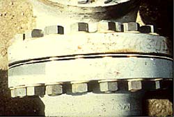
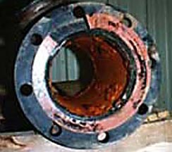
The scuba tank above suffered galvanic corrosion when the brass valve and the steel tank were wetted by condensation. Electrical isolation flanges like those shown on the right are used to prevent galvanic corrosion. Insulating gaskets, usually polymers, are inserted between the flanges, and insulating sleeves and washers isolate the bolted connections
The scuba tank above suffered galvanic corrosion when the brass valve and the steel tank were wetted by condensation. Electrical isolation flanges like those shown on the right are used to prevent galvanic corrosion. Insulating gaskets, usually polymers, are inserted between the flanges, and insulating sleeves and washers isolate the bolted connections.
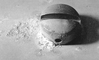
KSC conducts research on the effects of galvanic corrosion. The photo below shows the corrosion caused by a stainless steel screw causing galvanic corrosion of aluminum. The picture shows the corrosion resulting from only six months exposure at the Atmospheric Test Site.
Concentration Cell Corrosion
Concentration cell corrosion occurs when two or more areas of a metal surface are in contact with different concentrations of the same solution. There are three general types of concentration cell corrosion:
- metal ion concentration cells
- oxygen concentration cells, and
- active-passive cells.
Metal Ion Concentration Cells
In the presence of water, a high concentration of metal ions will exist under faying surfaces and a low concentration of metal ions will exist adjacent to the crevice created by the faying surfaces. An electrical potential will exist between the two points. The area of the metal in contact with the low concentration of metal ions will be cathodic and will be protected, and the area of metal in contact with the high metal ion concentration will be anodic and corroded. This condition can be eliminated by sealing the faying surfaces in a manner to exclude moisture. Proper protective coating application with inorganic zinc primers is also effective in reducing faying surface corrosion.
Oxygen Concentration Cells
A water solution in contact with the metal surface will normally contain dissolved oxygen. An oxygen cell can develop at any point where the oxygen in the air is not allowed to diffuse uniformly into the solution, thereby creating a difference in oxygen concentration between two points. Typical locations of oxygen concentration cells are under either metallic or nonmetallic deposits (dirt) on the metal surface and under faying surfaces such as riveted lap joints. Oxygen cells can also develop under gaskets, wood, rubber, plastic tape, and other materials in contact with the metal surface. Corrosion will occur at the area of low-oxygen concentration (anode). The severity of corrosion due to these conditions can be minimized by sealing, maintaining surfaces clean, and avoiding the use of material that permits wicking of moisture between faying surfaces.
Active-Passive Cells
Metals that depend on a tightly adhering passive film (usually an oxide) for corrosion protection; e.g., austenitic corrosion-resistant steel, can be corroded by active-passive cells. The corrosive action usually starts as an oxygen concentration cell; e.g., salt deposits on the metal surface in the presence of water containing oxygen can create the oxygen cell. If the passive film is broken beneath the salt deposit, the active metal beneath the film will be exposed to corrosive attack. An electrical potential will develop between the large area of the cathode (passive film) and the small area of the anode (active metal). Rapid pitting of the active metal will result. This type of corrosion can be avoided by frequent cleaning and by application of protective coatings.
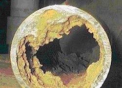
Pitting Corrosion
Passive metals, such as stainless steel, resist corrosive media and can perform well over long periods of time. However, if corrosion does occur, it forms at random in pits. Pitting is most likely to occur in the presence of chloride ions, combined with such depolarizers as oxygen or oxidizing salts. Methods that can be used to control pitting include maintaining clean surfaces, application of a protective coating, and use of inhibitors or cathodic protection for immersion service. Molybdenum additions to stainless steel (e.g. in 316 stainless) are intended to reduce pitting corrosion.
(Courtesy of www.eci-ndt.com)
The rust bubbles or tubercules on the cast iron above indicate that pitting is occurring. Researchers have found that the environment inside the rust bubbles is almost always higher in chlorides and lower in pH (more acidic) than the overall external environment. This leads to concentrated attack inside the pits.
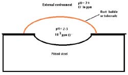
Similar changes in environment occur inside crevices, stress corrosion cracks, and corrosion fatigue cracks. All of these forms of corrosion are sometimes included in the term “occluded cell corrosion.”

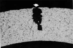
Pitting corrosion can lead to unexpected catastrophic system failure. The split tubing above left was caused by pitting corrosion of stainless steel. A typical pit on this tubing is shown above right.
Sometimes pitting corrosion can be quite small on the surface and very large below the surface. The figure below left shows this effect, which is common on stainless steels and other film-protected metals. The pitting shown below right (white arrow) led to the stress corrosion fracture shown by the black arrows.
A complete discussion of this corrosion is contained in Steven J. McDanels, “Failure Analysis Of Launch Pad Tubing From The Kennedy Space Center,” Microstructural Science, Vol. 25, 1998, ASM International, Materials Park, OH, pp. 125-129.
Crevice Corrosion
Crevice or contact corrosion is the corrosion produced at the region of contact of metals with metals or metals with nonmetals. It may occur at washers, under barnacles, at sand grains, under applied protective films, and at pockets formed by threaded joints. Whether or not stainless steels are free of pit nuclei, they are always susceptible to this kind of corrosion because a nucleus is not necessary.
Cleanliness, the proper use of sealants, and protective coatings are effective means of controlling this problem. Molybdenum-containing grades of stainless steel (e.g. 316 and 316L) have increased crevice corrosion resistance.

The crevice corrosion shown above happened when an aerospace alloy (titanium – 6 aluminum – 4 vanadium) was used instead of a more corrosion-resistant grade of titanium. Special alloying additions are added to titanium to make alloys which are crevice corrosion resistant even at elevated temperatures.
Screws and fasteners have are common sources of crevice corrosion problems. The stainless steel screws shown below corroded in the moist atmosphere of a pleasure boat hull.

(Courtesy of marinesurvey.com)
Filiform Corrosion
This type of corrosion occurs under painted or plated surfaces when moisture permeates the coating. Lacquers and “quick-dry” paints are most susceptible to the problem. Their use should be avoided unless absence of an adverse effect has been proven by field experience. Where a coating is required, it should exhibit low water vapor transmission characteristics and excellent adhesion. Zinc-rich coatings should also be considered for coating carbon steel because of their cathodic protection quality.
(Courtesy of www.cp.umist.ac.uk)
(Courtesy of www.cp.umist.ac.uk)
Filiform corrosion normally starts at small, sometimes microscopic, defects in the coating.


The picture on the left shows filiform corrosion causing bleed-through on a welded tank. The picture on the right shows “worm-like” filiform corrosion tunnels forming under a coating at the Atmospheric Test Site.
Filiform corrosion is minimized by careful surface preparation prior to coating, by the use of coatings that are resistant to this form of corrosion (see above), and by careful inspection of coatings to insure that holidays, or holes, in the coating are minimized.
Intergranular Corrosion
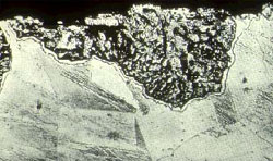
Intergranular corrosion is an attack on or adjacent to the grain boundaries of a metal or alloy. A highly magnified cross section of most commercial alloys will show its granular structure. This structure consists of quantities of individual grains, and each of these tiny grains has a clearly defined boundary that chemically differs from the metal within the grain center. Heat treatment of stainless steels and aluminum alloys accentuates this problem.

The picture above shows a stainless steel which corroded in the heat affected zone a short distance from the weld. This is typical of intergranular corrosion in austenitic stainless steels. This corrosion can be eliminated by using stabilized stainless steels (321 or 347) or by using low-carbon stainless grades (304L or 3I6L).
Heat-treatable aluminum alloys (2000, 6000, and 7000 series alloys) can also have this problem. See the section on exfoliation corrosion below.
Exfoliation Corrosion

Exfoliation is a form of intergranular corrosion. It manifests itself by lifting up the surface grains of a metal by the force of expanding corrosion products occurring at the grain boundaries just below the surface. It is visible evidence of intergranular corrosion and most often seen on extruded sections where grain thickness is less than in rolled forms. This form of corrosion is common on aluminum, and it may occur on carbon steel.
The picture on the left shows exfoliation of aluminum. Exfoliation of carbon steel is apparent in the channel on the coating exposure panel on the right. The expansion of the metal caused by exfoliation corrosion can create stresses that bend or break connections and lead to structural failure.
Stress Corrosion Cracking
Stress corrosion cracking (SCC) is caused by the simultaneous effects of tensile stress and a specific corrosive environment. Stresses may be due to applied loads, residual stresses from the manufacturing process, or a combination of both.

Cross sections of SCC frequently show branched cracks. This river branching pattern is unique to SCC and is used in failure analysis to identify when this form of corrosion has occurred.
The photo below shows SCC of an insulated stainless-steel condensate line. Water wetted the insulation and caused chlorides to leach from the insulation onto the hot metal surface. This is a common problem on steam and condensate lines. Control is by maintaining the jackets around the lines so that moisture doesn’t enter the insulation or is quickly drained off.

The next two photos show intergranular SCC of an aluminum aerospace part. The intergranular nature of the corrosion can be seen in the scanning electron microscope image on the left and in the microscopic cross section on the right. The arrows indicate the primary crack shown in both pictures. Note that secondary cracks are also apparent. These secondary cracks are common in stress corrosion cracking.


The failure above occurred on an aluminum alloy subjected to residual stresses and salt water. Changes in alloy heat treatment recommended by KSC Materials Laboratory eliminated this problem. McDanels, S. J., “An Overview of Fatigue and Other Metallurgical Failure Modes and Analysis at the Kennedy Space Center”, Flammability and Sensitivity of Materials in Oxygen-Enriched Atmospheres: Eight Volume, ASTM STP 1319, W. T. Royals, T. C. Chou, and T.A. Steinberg, Eds., American Society for Testing and Materials, 1997.
Corrosion Fatigue
Corrosion fatigue is a special case of stress corrosion caused by the combined effects of cyclic stress and corrosion. No metal is immune from some reduction of its resistance to cyclic stressing if the metal is in a corrosive environment. Damage from corrosion fatigue is greater than the sum of the damage from both cyclic stresses and corrosion. Control of corrosion fatigue can be accomplished by either lowering the cyclic stresses or by corrosion control.
The “beach marks” on the propeller shown below mark the progression of fatigue on this surface.

Similar beach marks are shown on the aerospace part below left. The high magnification scanning electron microscope image on the right shows striations (individual crack progression marks). The part shown below is also discussed in the section on fretting corrosion.


An infamous example of corrosion fatigue occured in 1988 on an airliner flying between the Hawaiian islands. This disaster, which cost one life, prompted the airlines to look at their airplanes and inspect for corrosion fatigue.

Fretting Corrosion
The rapid corrosion that occurs at the interface between contacting, highly loaded metal surfaces when subjected to slight vibratory motions is known as fretting corrosion.

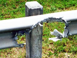
The photo above shows fretting corrosion of a fence post and wires which swing in the wind and wear against the post. Both the fence post and the connecting wires are experiencing fretting corrosion.
This type of corrosion is most common in bearing surfaces in machinery, such as connecting rods, splined shafts, and bearing supports, and often causes a fatigue failure. It can occur in structural members such as trusses where highly loaded bolts are used and some relative motion occurs between the bolted members.

(Courtesy of www.emersonbearing.com)
Fretting corrosion is greatly retarded when the contacting surfaces can be well lubricated as in machinery-bearing surfaces so as to exclude direct contact with air.
The bearing race above is a classic example of fretting corrosion. This is greatly retarded when the contacting surfaces can be well lubricated as in machinery-bearing surfaces so as to exclude direct contact with air.


The fretting on a large aluminum part (above left) led to deposits of debris (shown in the cross sections on the right). The vibratory motions rubbing back and forth also produced the fatigue cracks shown in the section on fatigue corrosion.
Erosion Corrosion
Erosion corrosion is the result of a combination of an aggressive chemical environment and high fluid-surface velocities. This can be the result of fast fluid flow past a stationary object, such as the case with the oil-field check valve shown on the left below, or it can result from the quick motion of an object in a stationary fluid, such as happens when a ship’s propeller churns the ocean.


Surfaces which have undergone erosion corrosion are generally fairly clean, unlike the surfaces from many other forms of corrosion.
Erosion corrosion can be controlled by the use of harder alloys (including flame-sprayed or welded hard facings) or by using a more corrosion resistant alloy. Alterations in fluid velocity and changes in flow patterns can also reduce the effects of erosion corrosion.
Erosion corrosion is often the result of the wearing away of a protective scale or coating on the metal surface. The oil field production tubing shown above on the right corroded when the pressure on the well became low enough to cause multiphase fluid flow. The impact of collapsing gas bubbles caused the damage at joints where the tubing was connected and turbulence was greater.
Many people assume that erosion corrosion is associated with turbulent flow. This is true, because all practical piping systems require turbulent flow-the fluid would not flow fast enough if lamellar (nonturbulent) flow were maintained. Most, if not all, erosion corrosion can be attributed to multiphase fluid flow. The check valve on the left above failed due to sand and other particles in an otherwise noncorrosive fluid. The tubing on the right failed due to the pressure differences caused when gas bubbles collapsed against the pipe wall and destroyed the protective mineral scale that was limiting corrosion.
Dealloying
Dealloying is a rare form of corrosion found in copper alloys, gray cast iron, and some other alloys. Dealloying occurs when the alloy loses the active component of the metal and retains the more corrosion resistant component in a porous “sponge” on the metal surface. It can also occur by redeposition of the noble component of the alloy on the metal surface. Control is by the use of more resistant alloys-inhibited brasses and malleable or nodular cast iron.

The brass on the left dezincified leaving a porous copper plug on the surface. The gray cast iron water pipe shown on the right photo has graphitized and left graphitic surface plugs which can be seen on the cut surface. The rust tubercules or bubbles are also an indication of pitting corrosion.
The bottom photo shows a layer of copper on the surface of a dealloyed 70% copper-30% nickel cupronickel heat exchanger tube removed from a ship. Stagnant seawater is so corrosive that even this normally corrosion-resistant alloy has corroded. Virtually all copper alloys are subject to dealloying in some environments.

Hydrogen Damage
Hydrogen can cause a number of corrosion problems. Hydrogen embrittlement is a problem with high-strength steels, titanium, and some other metals. Control is by eliminating hydrogen from the environment or by the use of resistant alloys.
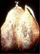
Hydrogen blistering can occur when hydrogen enters steel as a result of the reduction reaction on a metal cathode. Single-atom nacent hydrogen atoms then diffuse through the metal until they meet with another atom, usually at inclusions or defects in the metal. The resultant diatomic hydrogen molecules are then too big to migrate and become trapped. Eventually a gas blister builds up and may split the metal as shown in the picture below.

Hydrogen blistering is controlled by minimizing corrosion in acidic environments. It is not a problem in neutral or caustic environments or with high-quality steels that have low impurity and inclusion levels.


The broken spring above on the left was brought to the KSC Materials Laboratory for failure analysis. Examination at high magnification in the scanning electron microscope (above right) revealed intergranular cleavage characteristic of hydrogen assisted cracking (hydrogen embrittlement). The part was zinc plated during refurbishment, and the hydrogen which entered the metal during the plating process had not been baked out. A postplating bakeout procedure should be standard for high strength steels.
Corrosion in Concrete


The picture on the left shows cracking and staining of a seawall near the Kennedy Space Center. The pitting corrosion in the right photo occured on an aluminum railing on a concrete causeway over an inlet to the Atlantic Ocean.
Concrete is a widely-used structural material that is frequently reinforced with carbon steel reinforcing rods, post-tensioning cable or prestressing wires. The steel is necessary to maintain the strength of the structure, but it is subject to corrosion. The cracking associated with corrosion in concrete is a major concern in areas with marine environments (like KSC) and in areas which use deicing salts.
There are two theories on how corrosion in concrete occurs:
- Salts and other chemicals enter the concrete and cause corrosion. Corrosion of the metal leads to expansive forces that cause cracking of the concrete structure.
- Cracks in the concrete allow moisture and salts to reach the metal surface and cause corrosion.
Both possibilities have their advocates, and it is also possible that corrosion in concrete can occur either way. The mechanism isn’t truly important, the corrosion leads to damage, and the damage must be controlled.
In new construction, corrosion in concrete is usually controlled by embedding the steel deep enough so that chemicals from the surface don’t reach the steel (adequate depth of cover). Other controls include keeping the water/cement ratio below 0.4, having a high cement factor, proper detailing to prevent cracking and ponding, and the use of chemical admixtures. These methods are very effective, and most concrete structures, even in marine environments, do not corrode.
Unfortunately, some concrete structures do corrode. When this happens, remedial action can include repairing the cracked and spalled concrete, coating the surface to prevent further entry of corrosive chemicals into the structure, and cathodic protection, an electrical means of corrosion control. KSC has experience with all of these methods of controlling corrosion on existing concrete structures.
Microbial Corrosion
Microbial corrosion (also called microbiologically-influenced corrosion or MIC) is corrosion that is caused by the presence and activities of microbes. This corrosion can take many forms and can be controlled by biocides or by conventional corrosion control methods.
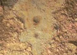
There are a number of mechanisms associated with this form of corrosion, and detailed explanations are available at the web sites listed at the bottom of this section. Most MIC takes the form of pits that form underneath colonies of living organic matter and mineral and biodeposits. This biofilm creates a protective environment where conditions can become quite corrosive and corrosion is accelerated.
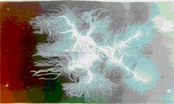
The picture below shows a biofilm on a metallic condenser surface. These biofilms can allow corrosive chemicals to collect within and under the films. Thus the corrosive conditions under a biofilm can be very aggressive, even in locations where the bulk environment is noncorrosive.
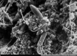
MIC can be a serious problem in stagnant water systems such as the fire-protection system that produced the pits shown above. The use of biocides and mechanical cleaning methods can reduce MIC, but anywhere where stagnant water is likely to collect is a location where MIC can occur.
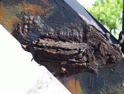
Corrosion (oxidation of metal) can only occur if some other chemical is present to be reduced. In most environments, the chemical that is reduced is either dissolved oxygen or hydrogen ions in acids. In anaerobic conditions (no oxygen or air present), some bacteria (anaerobic bacteria) can thrive. These bacteria can provide the reducible chemicals that allow corrosion to occur. That’s how the limited corrosion that was found on the hull of the Titanic occurred. The picture below shows a “rusticle” removed from the hull of Titanic. This combination of rust and organic debris clearly shows the location of rivet holes and where two steel plates overlapped.

(Courtesy of www.dbi.sk.ca)
Much microbial corrosion involves anaerobic or stagnant conditions, but it can also be found on structures exposed to air. The pictures below show a spillway gate from a hydroelectric dam on the Columbia River. The stress corrosion cracks were caused by pigeon droppings which produced ammonia-a chemical that causes stress corrosion cracking on copper alloys like the washers used on this structure. Since it’s impossible to potty train pigeons, a new alloy resistant to ammonia was necessary.


(Courtesy of www.meic.com)
In addition to the use of corrosion resistant alloys, control of MIC involves the use of biocides and cleaning methods that remove deposits from metal surfaces. Bacteria are very small, and it is often very difficult to get a metal system smooth enough and clean enough to prevent MIC.